Share to:
Related Products
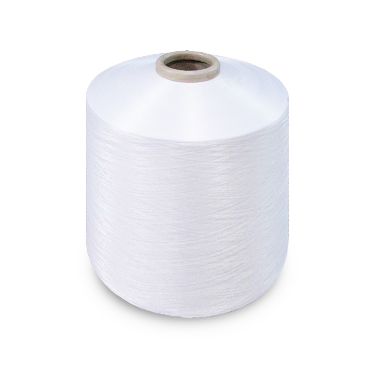
High quality factory price air covered yarn for knitting
LQ-16E2
Price: From $0.66
Delivery time: 9-20 days after payment
MOQ: 500 KG
The results show that the device is completed by the electrical control system, which can achieve automatic control without adding manpower; it can improve the retention rate of spinning and clean up the tail yarn on the waste spindle disc.
This page introduces how to keep the tail yarn when the collective doffing system is fully drawn and how to effectively handle the tail yarn on the waste spindle disc after the collective doffing system is completed. The results show that the device is completed by the electrical control system, which can achieve automatic control without adding manpower; it can improve the retention rate of spinning and clean up the tail yarn on the waste spindle disc.
When the ring spinning frame uses the collective doffing system, in order to improve the retention rate of driving, so that there are more tails wound on the spindle waste disc, which are usually controlled at 3-5 turns. The yarn is tightly wound and cannot be cleaned automatically. When it accumulates to a certain extent, the retention rate of the spinning frame will be reduced, which requires manual cleaning of the tails. Especially in spinning coarse count yarn, the spinning time is short, the cleaning times are more frequent, it needs cleaning once a day, the workload is large, and the labor intensity is high. Ring spinning frame is an important equipment in the cotton spinning production process. It has the largest number, large amount of labor and high labor intensity. In order to better handle the tail yarn automatically, the main cleaning methods on the market at present include automatic yarn clamping, automatic tail yarn clearing and the use of new structural spindles which can overcome the defects of the tail yarn retaining device.

1 working principle of yarn clamping and tail yarn cleaning device
The clip and tail yarn cleaning device can be added on the basis of not changing the original spinning frame structure, which is easy to install and does not affect the spinning performance of the ring spinning frame. This device is controlled by electrical automation program, so it needs to add control program and control node to the original spinning program. The device is mainly designed according to the principle of A-frame structure, so that the long-term motion relative to the spinning frame becomes the transverse motion. By adjusting the control program of the spinning frame, when the ring spinning frame is doffing, the tail yarn wound on the waste disc is controlled at 1-1.5 turns, so as to reduce the winding amount of the tail yarn. When the collective doffing system is full of yarn tubes, the tail yarn can be retained basically because the tail yarn is held by a clamping device. After the operation of collective yarn dropping system, the empty bobbin presses the tail yarn, and the electric control system controls the air cylinder to return to the original position, so that the yarn gripper leaves the waste disc. As the tail yarn wound on the waste disc is only 1-1.5 turns, when the spinning machine starts, the spindle rotates at high speed, and the tail yarn is thrown out by the centrifugal force of the spindle rotation, so as to achieve the effect of cleaning the tail yarn.

2 main structure of yarn clamping and tail yarn cleaning device
The air source is used as the power of the clamping and tail yarn cleaning device, and the piston cylinder moves in the form of A-frame connecting rod mechanism. The cylinder moves to drive the A-frame connecting rod mechanism, so that the shovel claw combination can produce a clamping force to hold the tail yarn wound on the spindle waste silk disk when the yarn is falling. Its main parts include cylinder seat, cylinder, cylinder joint, sliding flat iron, cylinder fixed seat, sliding seat, long and short herringbone arms, flat steel, fixed bracket, etc. The following are the specific functions of each part.
1) the cylinder seat is used to fix the cylinder and prevent the cylinder from moving under the action of axial force.
2) the air cylinder provides the driving force for the yarn clamping and tail yarn cleaning device. Under the action of the air cylinder, the yarn clamping and tail yarn cleaning device moves to the yarn clamping position and returns to the initial position.
3) the cylinder joint makes the cylinder piston rod and the sliding flat iron fixed together, and plays the role of connecting the cylinder and the sliding flat iron, so that when the cylinder piston rod moves, it can drive the sliding flat iron to move.
4) the sliding flat iron connects the short herringbone arm and the cylinder joint, so that the axial movement of the cylinder can drive the short herringbone arm movement and self rotation movement through the sliding flat iron.
5) the fixed seat of the air cylinder, so that the air cylinder can be firmly fixed on the air cylinder seat.
6) the slide seat supports and guides the slide flat iron, so that the slide flat iron can be controlled in the long-term movement, and the up and down deviation from the left and right can be avoided. During the movement, the level can be guaranteed. The material of the slide seat is powder metallurgy, which plays a lubricating role. Support and fix the short herringbone arm at the same time.
7) the long herringbone arm decomposes and transforms the long-term movement force of the sliding flat iron through the short herringbone arm, and drives the short herringbone arm to move.
8) the short herringbone arm is fixed on the sliding seat through one end, and the other end is connected with the middle hole of the long herringbone arm, so as to convert the long-term movement of the long herringbone arm into the transverse movement of the long herringbone arm and drive the transverse movement of the flat iron.
9) the flat steel is mainly used to fix the shovel claw and connect the long herringbone arm, and ensure that the shovel claw is on the same horizontal plane.
10) the shovel claw, through the elastic parts on the shovel claw, holds the tail yarn at the tail yarn position of the spindle waste silk disk, and clamps the tail yarn to prevent the tail yarn from falling off during the collective yarn dropping process, resulting in the breaking of the driving head.
11) the pin is mainly used to connect and fix the long herringbone arm, short herringbone arm, sliding flat iron, sliding seat and flat steel, and ensure that they can move relative to each other to reduce unnecessary friction.
12) the fixing bracket is mainly used to support and fix the sliding seat, so that the yarn clamping and tail cleaning device is fixed on the main machine, playing a positioning role.
In addition to the above mechanical parts structure, the yarn clamping and tail yarn cleaning device also needs to add electrical auxiliary equipment. The main parts include five position three-way solenoid valve, air pipe, two-way connector, three-way connector, magnetic switch, photoelectric switch, etc. In addition, the electric control system program needs to add the control program of the yarn clamping and tail yarn cleaning device to ensure the automatic operation of the yarn clamping and tail yarn cleaning device.


